cn
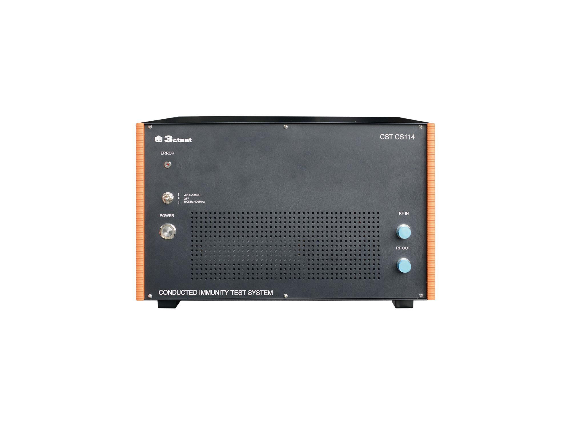
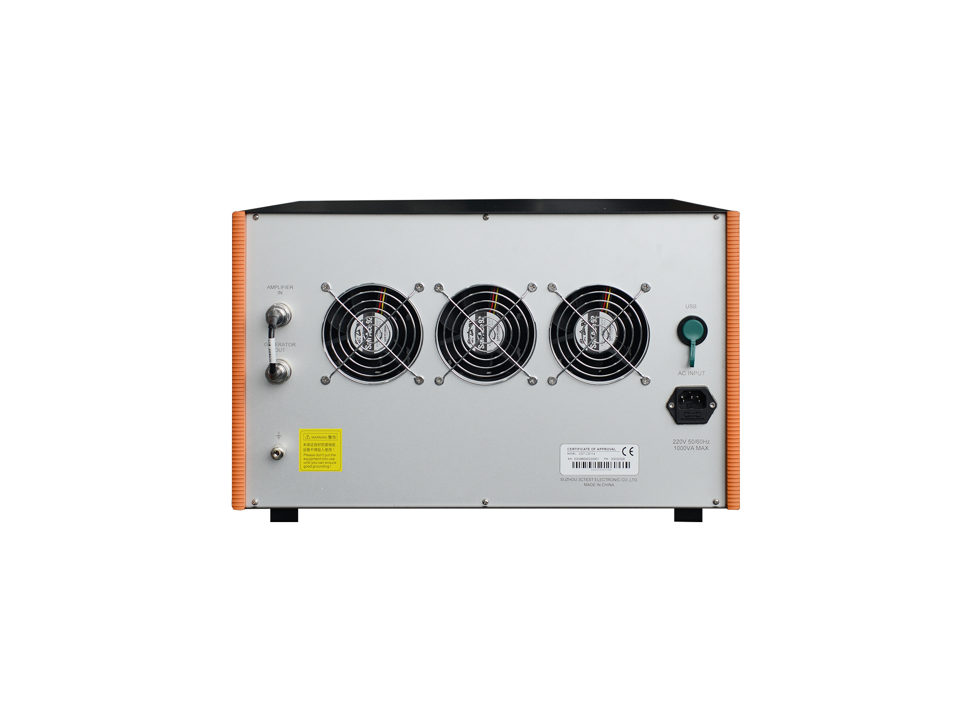
Conducted Immunity Test System_CST CS114
  • Conducted Immunity Test System_CST CS114
  • Conducted Immunity Test System_CST CS114

Conducted Immunity Test System
CST CS114

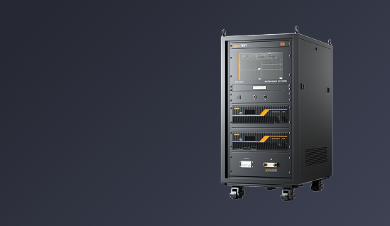
The CST CS114 conducted immunity test system is an integrated automatic test system in accordance with MIL-STD-461H, MIL-STD-461G and RTCA DO-160, specifically for cable injection conducted susceptibility testing of military electronic products. 

Introduction

The CST CS114 conducted immunity test system is an integrated automatic test system in accordance with MIL-STD-461H, MIL-STD-461G and RTCA DO-160, specifically for cable injection conducted susceptibility testing of military electronic products. Adopting a highly integrated design, it comes with a built-in signal generator, RF power amplifier and RF power meter, greatly reducing setup costs and system complexity. Built-in wide dynamic range power meter ensures real-time and precise monitoring, stable test procedures and reliable measurement results. Output frequency range of the test system is 4 kHz ~ 400 MHz. The test system is also compatible with bulk current injection (BCI) immunity tests for automotive electronics as per ISO 11452-4 and GB/T 33014.4.


The whole test system, centrally controlled by EMC (CS114) software (this product requires the software for operation), can improve system scalability and test efficiency. Test results support one-click saving, printing and internal enterprise sharing.


Calibration-System Setup:


cs114.png


① PC Software: EMC(CS114)

② Main Unit: CST CS114

③ Attenuator: AT150-30dB-1G-NF-NF

③ Attenuator: AT150-6dB-6G-NM-NF-B

④ Coaxial Load: TF80

⑤ Coaxial Load: TF80

⑥ Current Injection Clamp Calibration Fixture: BCICF-500

⑦ Current Injection Clamp: BCIP-500

⑧ Calibration Fixture for Broadband Current Monitoring Clamp: WCMCF 500

⑨ Broadband Current Monitoring Clamp: T-52

⑩ Attenuator: AT150-30dB-1G-NF-NF

⑩ Attenuator: AT150-6dB-6G-NM-NF-B

⑩ Attenuator: AT5-20dB -1G-NF-NM-B


Verification-System Setup:


cs114-1.png


① PC Software: EMC(CS114)

② Main Unit: CST CS114

③ Attenuator: AT150-30dB-1G-NF-NF

③ Attenuator: AT150-6dB-6G-NM-NF-B

④ Attenuator: AT150-30dB-1G-NF-NF

④ Attenuator: AT150-6dB-6G-NM-NF-B

④ Attenuator: AT5-20dB -1G-NF-NM-B

⑤ Coaxial Load: TF80

⑥ Current Injection Clamp Calibration Fixture: BCICF-500

⑦ Current Injection Clamp: BCIP-500

⑧ Calibration Fixture for Broadband Current Monitoring Clamp: WCMCF 500

⑨ Broadband Current Monitoring Clamp: T-52

⑩ Coaxial Load: TF80

Features

> Highly integrated design with built-in signal generator, RF power amplifier and power meter

> Built-in an internal wide dynamic range power meter for real-time and precise monitor (-60 dBm ~ +20 dBm)

> Stable and Reliable Broadband Power Amplifier (4 kHz ~ 400 MHz)

> Support high-precision closed-loop test with traceable results, and support optional current monitoring probe and closed-loop test method supported

> Automated test procedures double testing efficiency

> High-stability hardware for worry-free long-term operation

> Support monitoring and overrange protection functions for temperature, VSWR and power

Standards
ISO Standards
MIL Standards
Aerospace Standards
GJB Standards
View All Standards
Specification
Technical Parameters
RF Signal Generator
Frequency4 kHz ~ 3 GHz
Frequency Resolution0.23 Hz
Frequency Temperature Stability±0.5 ppm
Harmonics≤ -30 dBc
Non-Harmonic≤ -50 dBc
Output Power-120 dBm ~ 0dBm(2 kHz ~ 500 kHz)
-120 dBm ~ +10dBm(500 kHz ~ 3 GHz)
Power Accuracy±1.0 dB
Resolution0.1 dB
Internal Modulation Source (LF)Sine wave 0.1 Hz ~ 500 kHz
Square wave 0.1 Hz ~ 20 kHz
Triangular wave/Sawtooth wave 0.1 Hz ~ 100 kHz
Amplitude Modulation (AM)Modulation depth: 0% ~ 100%
Modulation frequency: 20 Hz ~ 1 MHz
Frequency Modulation (FM)Max Frequency Deviation: 5 MHz
Modulation frequency: 20 Hz ~ 1 MHz
Phase Modulation (ФM)Phase deviation range: 0° ~ 360°
Modulation frequency: 1 Hz ~ 25 kHz
Output PortN-Female
VSWR<1.5
Power Amplifier
Frequency4 kHz ~ 400 MHz
Output Power
(1 dB compression point)
>100 W
VSWR< 1.5
Output Impedance50 Ω
Output PortN-Female
Power Meter
Frequency4 kHz ~ 3 GHz
Measurement Range-60 dBm ~ +20 dBm
Measurement Accuracy±0.5 dB
Input PortN-Female
VSWR< 1.3
General Parameters
Accessories
Optional Accessories
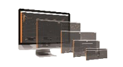
1Test Software
(This series of products shall be used with this software.)
Model: EMC (CS114)
A RF conducted immunity test software for the CST series; support Windows 10 and USB communication; enable remote calibration and test operations
Test Software
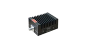
2Attenuator

Model: AT150-6dB-6G-NM-NF-B

Frequency: DC ~ 6 GHz

Attenuation value: 6 dB
Power: 150 W
Attenuator
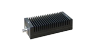
3Attenuator

Model: AT150-30dB-1G-NF-NF

Frequency: DC ~ 1 GHz

Attenuation value: 30 dB
Power: 150 W
Attenuator
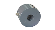
4Coaxial LoadModel: TF80
Frequency: DC ~ 1 GHz
Impedance: 50 Ω
Power: 80 W
Coaxial Load
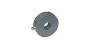
5Current Injection ClampModel: BCIP-500
Frequency: 2 kHz ~ 500 MHz
Power: 100 W (30 min cont.)
Power: 150 W (15 min cont.)
Power: 200 W (5 min cont.)
Interface: N
Inner Diameter: 40 mm
Outer Diameter: 127 mm
Height: 70 mm
Current Injection Clamp
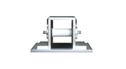
6Current Injection Clamp Calibration FixtureModel: BCICF-500
Frequency: DC ~ 500 MHz
Characteristic Impedance: 50 Ω
Inner Body Diameter: 40 mm
Inner Length: 100 mm
Inner Width: 127 mm
Inner Height: 135 mm
Current Injection Clamp Calibration Fixture
7Broadband Current Monitoring ClampModel: T-52
Frequency: 2 kHz ~ 400 MHz
Transfer Impedance: 2.5 Ω (8 dBΩ)
Inner Diameters: 40 mm
Outer Diameters: 127 mm
Height: 40 mm
RF Current: 2 A
Pulse Current: 100 A
Broadband Current Monitoring Clamp
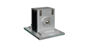
8Calibration Fixture for Broadband Current Monitoring ClampModel: WCMCF 500
Frequency: DC ~ 500 MHz
Characteristic impedance: 50 Ω
Inner diameter: 40 mm
Internal length: 64 mm
Internal width: 127 mm
Internal height: 132 mm
wcmcf500.png
Standard Accessories

Power Cord, RF Cable, Attenuator AT5-20dB, Grounding Wire, USB Cable, Snap-on Ferrite Core, User Manual

CST Series Comparison
ModelPower Amplifier Parameters
FrequencyGain
CST 10200C4 kHz ~ 400 MHz53 dB ± 1 dB (200 W)
CST CS1144 kHz ~ 400 MHz50 dB ± 1 dB (100 W)
CST CS114(2 kHz)2 kHz ~ 400 MHz50 dB ± 1 dB (100 W)

The working frequency of CST CS114(2 kHz) signal generator:2 kHz ~ 3 GHz

Request a Quote
Interested in our products? Leave us a message, and our team will get back to you soon!
  • Search Engine
  • Industry Exhibition / Trade Show
  • Social Media
  • Online Advertisement
  • Industry Publication
  • Business Partner / Distributor
  • Colleague or Industry Contact
  • Existing Customer
  • Other
I agree to the  Privacy Policy.

If you have any questions, feel free to Contact Us!

Prev: Conducted Immunity Test System Next: Conducted Immunity Test System Back to list
Request a Quote Now
Conducted Immunity Test System
CST CS114
  • Search Engine
  • Industry Exhibition / Trade Show
  • Social Media
  • Online Advertisement
  • Industry Publication
  • Business Partner / Distributor
  • Colleague or Industry Contact
  • Existing Customer
  • Other
Quote List0
Compare0
Selection
Top
Compary
Add up to 5 product comparisons for each type.
Only compare the currently expanded module.