
High frequency recommended vocabulary
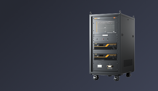
The Lightning Direct Effects Test System LCG 464C is an advanced high-energy pulsed current test platform specifically designed to simulate the current impact process experienced by aircraft during direct lightning events.
During flight under severe convective weather conditions, aircraft may be subjected to direct lightning attachment. The transient high-current pulses, high energy density, intense electromagnetic fields, and arc effects generated by lightning can cause severe impacts on aircraft structures, composite materials, fuel systems, and onboard equipment, including material ablation, localized melting, burning, potential explosion hazards, structural deformation, and degradation of mechanical strength.
The Lightning Direct Effects Test System LCG 464C is an advanced high-energy pulsed current test platform specifically designed to simulate the current impact process experienced by aircraft during direct lightning events. The system is used for aircraft-level lightning direct effects testing, as well as the verification of lightning protection performance for aerospace structures, composite materials, components, and critical equipment.
The system is widely applied in the aerospace and defense industries, supporting lightning protection evaluation and qualification testing for complete aircraft, airframe structures, aerospace composite materials, naval vessels, missiles, military vehicles, radar systems, and other critical equipment.
System Overview:
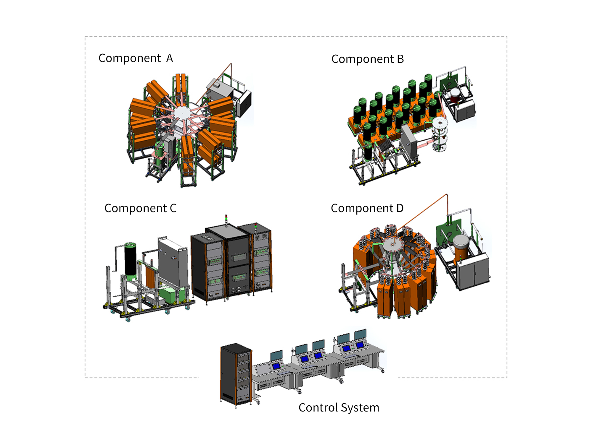
The lightning direct effects test system consists of five independent units, one control unit, and four high-energy current generators dedicated to generating DO-160 Section 23 lightning current components A, B, C, and D. All generator units communicate via an industrial fieldbus network, supporting both standalone operation of each generator and integrated centralized control of the complete system.
The system supports programmable multi-component lightning current waveform sequencing, enabling automatic consecutive generation of Components A, AH, B, C, C*, and D with adjustable time intervals between each waveform.

| Component A | Component B |
|
|
| Component C | Component D |
|
|
| Control System | |
| |
> The system can generate six different waveforms
> A rotary mechanism is adopted to automatically switch the charging polarity
> Electrical safety interlocks and automatic capacitor discharge functions are integrated to ensure operator safety
> A gapless Crowbar feedback circuit is employed to achieve oscillation-free waveforms.
> Control signals between the control unit and the main generator unit are transmitted via optical fiber isolation
> Each generator operates independently with its own dedicated control system
> Multiple test modes can be freely programmed to meet various waveform requirements within the specified test range
> The centralized control system can simultaneously operate up to four generators, enabling one-click execution of complete test sequences
> Multiple pneumatic switching units are used for high-voltage circuit switching, allowing automatic waveform configuration and switching.

 Phone: +86-512-68413700
 Email: info@3ctest.cn
 Address:No.99 E'meishan Rd, SND, Suzhou, Jiangsu, 215153, China,Suzhou, Jiangsu, 215153, China



© 2025 Suzhou 3CTEST


 Leave a Message