
cn
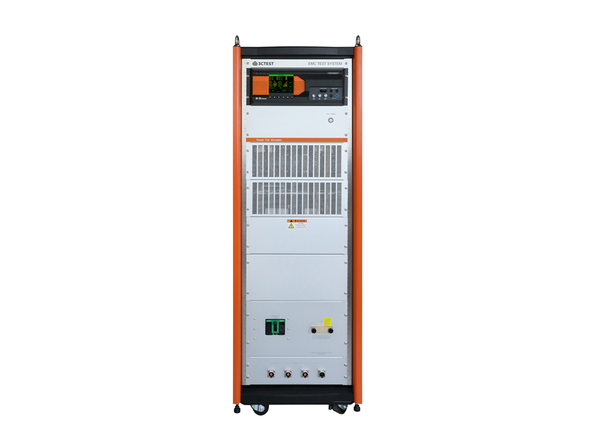
Power Failure Simulator_PFS 69200T1F
  • Power Failure Simulator_PFS 69200T1F

Power Failure Simulator
PFS 69200T1F

The PFS 69200T1F Power Failure Simulator is designed in accordance with the requirements of IEC 61000-4-11/34 to simulate voltage dips and short interruptions at the input port. 

Introduction

The PFS 69200T1F Power Failure Simulator is designed in accordance with the requirements of IEC 61000-4-11/34 to simulate voltage dips and short interruptions at the input port. These voltage variations are typically caused by faults in power grids and substation equipment, or sudden large changes in load status. Testing such phenomena is intended to verify whether electrical and electronic equipment can avoid unsafe operating conditions when subjected to abrupt voltage changes.


The PFS 69200T1F is equipped with controllable semiconductor switches that can withstand instantaneous inrush currents exceeding 1,000 A and provides electronic short-circuit protection.

Features

> 5.7-inch color touchscreen for front panel operation

> Support current and voltage measurement acquisition function

> Built-in multi-functional test modules

> Support voltage limiting, current limiting, overvoltage and over current function

> Ethernet RJ45 interface for PC remote control and test report printing

Standards
GB/T Standards
Specification
Technical Parameters
EUT Current/Voltage MeasurementLCD display
EUT Max. Continuous Current202 A
EUT Max. Input Voltage690 V AC, 50/60 Hz
Inrush Current Withstand Capability>1,000 A
ProtectionBuilt-in overcurrent, short-circuit, overvoltage, overtemperature, surge, EFT/burst and ESD protection.
Optional external protection accessories for Line in/Line out ports (e.g. warning lights, emergency stop buttons)
Interruption Level0%
Voltage Dip Level0%, 40%, 70%, 80%
Voltage Dip and Interruption Duration0.3 ~ 9,999 cycles or 10 ms ~ 99,999 ms
Voltage Dip and Interruption Interval50 ms ~ 50,000 ms
Voltage Dip and Interruption Counter1 ~ 9,999
Voltage Dip and Interruption Rise/Fall TimeFor generators with a rated current of ≤75 A: 1μs ~ 5 μs
(Resistor verification as specified in the standard)
For generators with a rated current > 75 A: 1 μs ~ 50 μs
(Resistor verification as specified in the standard)
Synchronization0° ~ 360°, 1° step setting or random mode
Trigger ModeManual, automatic, external trigger input
General Parameters
Accessories
Optional Accessories
1Immunity Test SoftwareModel: CoreLab
> Support Windows 7/8/10 /11
> Supports Ethernet and serial communication modes
> Supports parameter sequence, test sequences, easy for operation
> Supports customer information configuration and automatic test report printing.
CoreLab.png
2Calibration Impedance BoxModel: R100Ω/1134
Impedance: 100 Ω
Accuracy: ± 10%
Power: 2,000 W
Generator rated current: ≤50 A
R25.png
Model: R50Ω/1134
Impedance: 50 Ω
Accuracy: ± 10%
Power: 3,000 W
Generator rated current: 50 A<I≤100 A
Model: R25Ω/1134
Impedance: 25 Ω
Accuracy: ± 10%
Power: 6,000 W
Generator rated current: >100 A
Standard Accessories

Power Cord, Test Cable, Fuse, Grounding Wire, RF Cable, Flat Grounding Wire, User Manual


Request a Quote
Interested in our products? Leave us a message, and our team will get back to you soon!
  • Search Engine
  • Industry Exhibition / Trade Show
  • Social Media
  • Online Advertisement
  • Industry Publication
  • Business Partner / Distributor
  • Colleague or Industry Contact
  • Existing Customer
  • Other
I agree to the  Privacy Policy.

If you have any questions, feel free to Contact Us!

Prev: DC Power Failure Simulator Next: None Back to list
Request a Quote Now
Power Failure Simulator
PFS 69200T1F
  • Search Engine
  • Industry Exhibition / Trade Show
  • Social Media
  • Online Advertisement
  • Industry Publication
  • Business Partner / Distributor
  • Colleague or Industry Contact
  • Existing Customer
  • Other
Quote List0
Compare0
Selection
Top
Compary
Add up to 5 product comparisons for each type.
Only compare the currently expanded module.