
cn
Conducted Immunity Test System_CST CS114(2kHz)
  • Conducted Immunity Test System_CST CS114(2kHz)
  • Conducted Immunity Test System_CST CS114(2kHz)

Conducted Immunity Test System
CST CS114(2kHz)

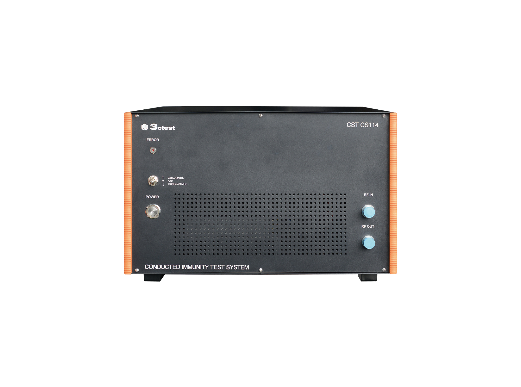
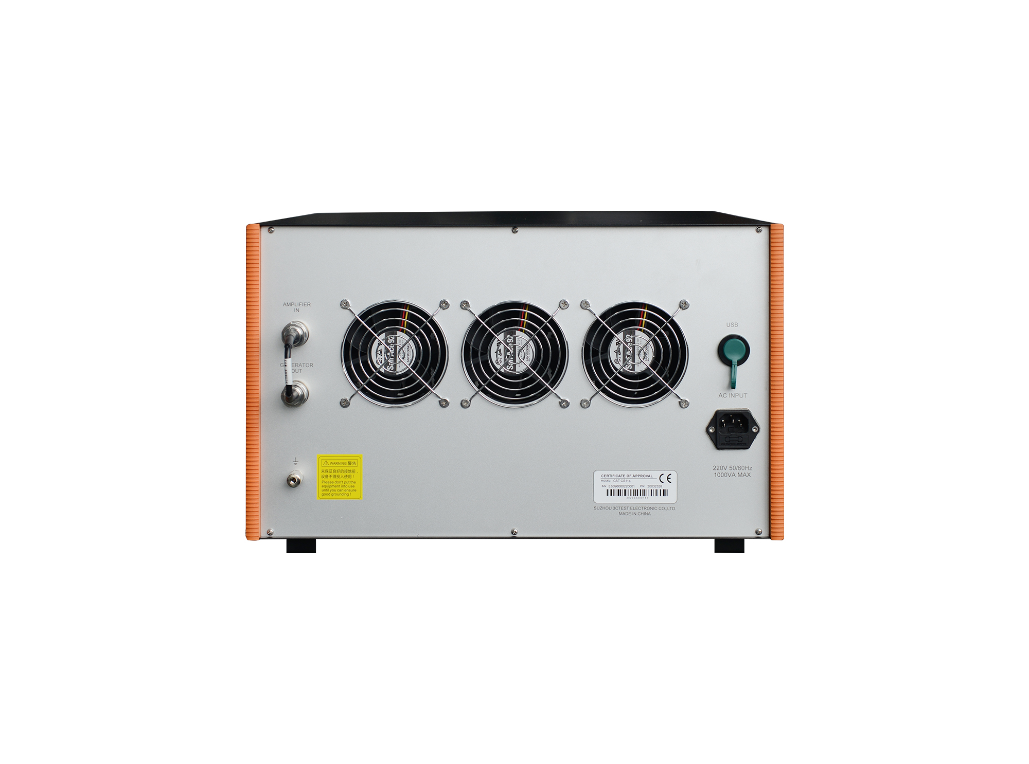
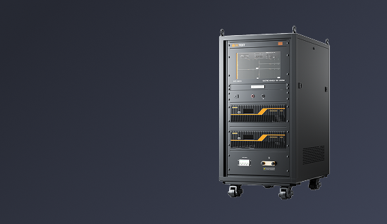
The CST CS114(2 kHz) conducted immunity test system is an integrated automatic test system in accordance with MIL-STD-461H, MIL-STD-461G and RTCA DO-160, specifically for cable injection conducted susceptibility testing of military electronic products. 

Introduction

The CST CS114(2 kHz) conducted immunity test system is an integrated automatic test system in accordance with MIL-STD-461H, MIL-STD-461G and RTCA DO-160, specifically for cable injection conducted susceptibility testing of military electronic products. Adopting a highly integrated design, it comes with a built-in signal generator, RF power amplifier and RF power meter, greatly reducing setup costs and system complexity. Built-in wide dynamic range power meter ensures real-time and precise monitoring, stable test procedures and reliable measurement results. Output frequency range of the test system is 2 kHz ~ 400 MHz. The test system is also compatible with bulk current injection (BCI) immunity tests for automotive electronics as per ISO 11452-4 and GB/T 33014.4.


The whole test system, centrally controlled by EMC (CS114) software (this product requires the software for operation), can improve system scalability and test efficiency. Test results support one-click saving, printing and internal enterprise sharing.


Calibration-System Setup:


cs114.png


① PC Software: EMC(CS114)

② Main Unit: CST CS114(2 kHz)

③ Attenuator: AT150-30dB-1G-NF-NF

③ Attenuator: AT150-6dB-6G-NM-NF-B

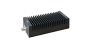
④ Coaxial Load: TF80

⑤ Coaxial Load: TF80

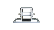
⑥ Current Injection Clamp Calibration Fixture: BCICF-500

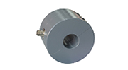
⑦ Current Injection Clamp: BCIP-500

⑧ Calibration Fixture for Broadband Current Monitoring Clamp: WCMCF 500

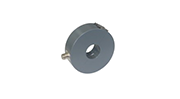
⑨ Broadband Current Monitoring Clamp: T-52

⑩ Attenuator: AT150-30dB-1G-NF-NF

⑩ Attenuator: AT150-6dB-6G-NM-NF-B

⑩ Attenuator: AT5-20dB -1G-NF-NM-B


Verification-System Setup:


cs114-1.png


① PC Software: EMC(CS114)

② Main Unit: CST CS114(2 kHz)

③ Attenuator: AT150-30dB-1G-NF-NF

③ Attenuator: AT150-6dB-6G-NM-NF-B

④ Attenuator: AT150-30dB-1G-NF-NF

④ Attenuator: AT150-6dB-6G-NM-NF-B

④ Attenuator: AT5-20dB -1G-NF-NM-B

⑤ Coaxial Load: TF80

⑥ Current Injection Clamp Calibration Fixture: BCICF-500

⑦ Current Injection Clamp: BCIP-500

⑧ Calibration Fixture for Broadband Current Monitoring Clamp: WCMCF 500

⑨ Broadband Current Monitoring Clamp: T-52

⑩ Coaxial Load: TF80

Features

> Highly integrated design with built-in signal generator, RF power amplifier and power meter

> Built-in an internal wide dynamic range power meter for real-time and precise monitor (-60 dBm ~ +20 dBm)

> Stable and Reliable Broadband Power Amplifier (2 kHz ~ 400 MHz)

> Support high-precision closed-loop test with traceable results, and support optional current monitoring probe and closed-loop test method supported

> Automated test procedures double testing efficiency

> High-stability hardware for worry-free long-term operation

> Support monitoring and overrange protection functions for temperature, VSWR and power

Standards
GJB Standards
Specification
Technical Parameters
RF Signal Generator
Frequency2 kHz ~ 3 GHz
Frequency Resolution0.23 Hz
Frequency Temperature Stability±0.5 ppm
Harmonics≤ -30 dBc
Non-Harmonic≤ -50 dBc
Output Power-120 dBm ~ 0dBm(2 kHz ~ 500 kHz)
-120 dBm ~ +10dBm(500 kHz ~ 3 GHz)
Power Accuracy±1.0 dB
Resolution0.1 dB
Internal Modulation Source (LF)Sine wave 0.1 Hz ~ 500 kHz
Square wave 0.1 Hz ~ 20 kHz
Triangular wave/Sawtooth wave 0.1 Hz ~ 100 kHz
Amplitude Modulation (AM)Modulation depth: 0% ~ 100%
Modulation frequency: 20 Hz ~ 1 MHz
Frequency Modulation (FM)Max Frequency Deviation: 5 MHz
Modulation frequency: 20 Hz ~ 1 MHz
Phase Modulation (ФM)Phase deviation range: 0° ~ 360°
Modulation frequency: 1 Hz ~ 25 kHz
Output PortN-Female
VSWR<1.5
Power Amplifier
Frequency2 kHz ~ 400 MHz
Output Power
(1 dB compression point)
>100 W
VSWR< 1.5
Output Impedance50 Ω
Output PortN-Female
Power Meter
Frequency2 kHz ~ 3 GHz
Measurement Range-60 dBm ~ +20 dBm
Measurement Accuracy±0.5 dB
Input PortN-Female
VSWR< 1.3
General Parameters
Accessories
Optional Accessories
1Test Software
(This series of products shall be used with this software.)
Model: EMC (CS114)
A RF conducted immunity test software for the CST series; support Windows 10 and USB communication; enable remote calibration and test operations
Test Software
2Attenuator

Model: AT150-6dB-6G-NM-NF-B

Frequency: DC ~ 6 GHz

Attenuation value: 6 dB
Power: 150 W
Attenuator
3Attenuator

Model: AT150-30dB-1G-NF-NF

Frequency: DC ~ 1 GHz

Attenuation value: 30 dB
Power: 150 W
Attenuator
4Coaxial LoadModel: TF80
Frequency: DC ~ 1 GHz
Impedance: 50 Ω
Power: 80 W
Coaxial Load
5Current Injection ClampModel: BCIP-500
Frequency: 2 kHz ~ 500 MHz
Power: 100 W (30 min cont.)
Power: 150 W (15 min cont.)
Power: 200 W (5 min cont.)
Interface: N
Inner Diameter: 40 mm
Outer Diameter: 127 mm
Height: 70 mm
Current Injection Clamp
6Current Injection Clamp Calibration FixtureModel: BCICF-500
Frequency: DC ~ 500 MHz
Characteristic Impedance: 50 Ω
Inner Body Diameter: 40 mm
Inner Length: 80 mm
Inner Width: 127 mm
Inner Height: 135 mm
Current Injection Clamp Calibration Fixture
7Broadband Current Monitoring ClampModel: T-52
Frequency: 2 kHz ~ 400 MHz
Transfer Impedance: 2.5 Ω (8 dBΩ)
Inner Diameters: 40 mm
Outer Diameters: 127 mm
Height: 40 mm
RF Current: 2 A
Pulse Current: 100 A
Broadband Current Monitoring Clamp
8Calibration Fixture for Broadband Current Monitoring ClampModel: WCMCF 500
Frequency: DC ~ 500 MHz
Characteristic impedance: 50 Ω
Inner diameter: 40 mm
Internal length: 64 mm
Internal width: 127 mm
Internal height: 132 mm
wcmcf500.png
Standard Accessories

Power Cord, RF Cable, Attenuator AT5-20dB, Grounding Wire, USB Cable, Snap-on Ferrite Core, User Manual

CST Series Comparison
ModelPower Amplifier Parameters
FrequencyGain
CST 10200C4 kHz ~ 400 MHz53 dB ± 1 dB (200 W)
CST CS1144 kHz ~ 400 MHz50 dB ± 1 dB (100 W)
CST CS114(2 kHz)2 kHz ~ 400 MHz50 dB ± 1 dB (100 W)

The working frequency of CST CS114(2 kHz) signal generator:2 kHz ~ 3 GHz

Request a Quote
Interested in our products? Leave us a message, and our team will get back to you soon!
  • Search Engine
  • Industry Exhibition / Trade Show
  • Social Media
  • Online Advertisement
  • Industry Publication
  • Business Partner / Distributor
  • Colleague or Industry Contact
  • Existing Customer
  • Other
I agree to the  Privacy Policy.

If you have any questions, feel free to Contact Us!

Prev: Conducted Immunity Test System Next: None Back to list
Request a Quote Now
Conducted Immunity Test System
CST CS114(2kHz)
  • Search Engine
  • Industry Exhibition / Trade Show
  • Social Media
  • Online Advertisement
  • Industry Publication
  • Business Partner / Distributor
  • Colleague or Industry Contact
  • Existing Customer
  • Other
Quote List0
Compare0
Selection
Top
Compary
Add up to 5 product comparisons for each type.
Only compare the currently expanded module.