
High frequency recommended vocabulary
The LVG Series complies with relevant standards, including IEC 60060-1, IEC 60060-2, IEC 61010, GB 311, GB/T 16927.1-2011, GB/T 16927.2-2011, and GB/T 116896.1-2011.
The LVG Series complies with relevant standards, including IEC 60060-1, IEC 60060-2, IEC 61010, GB 311, GB/T 16927.1-2011, GB/T 16927.2-2011, and GB/T 116896.1-2011.
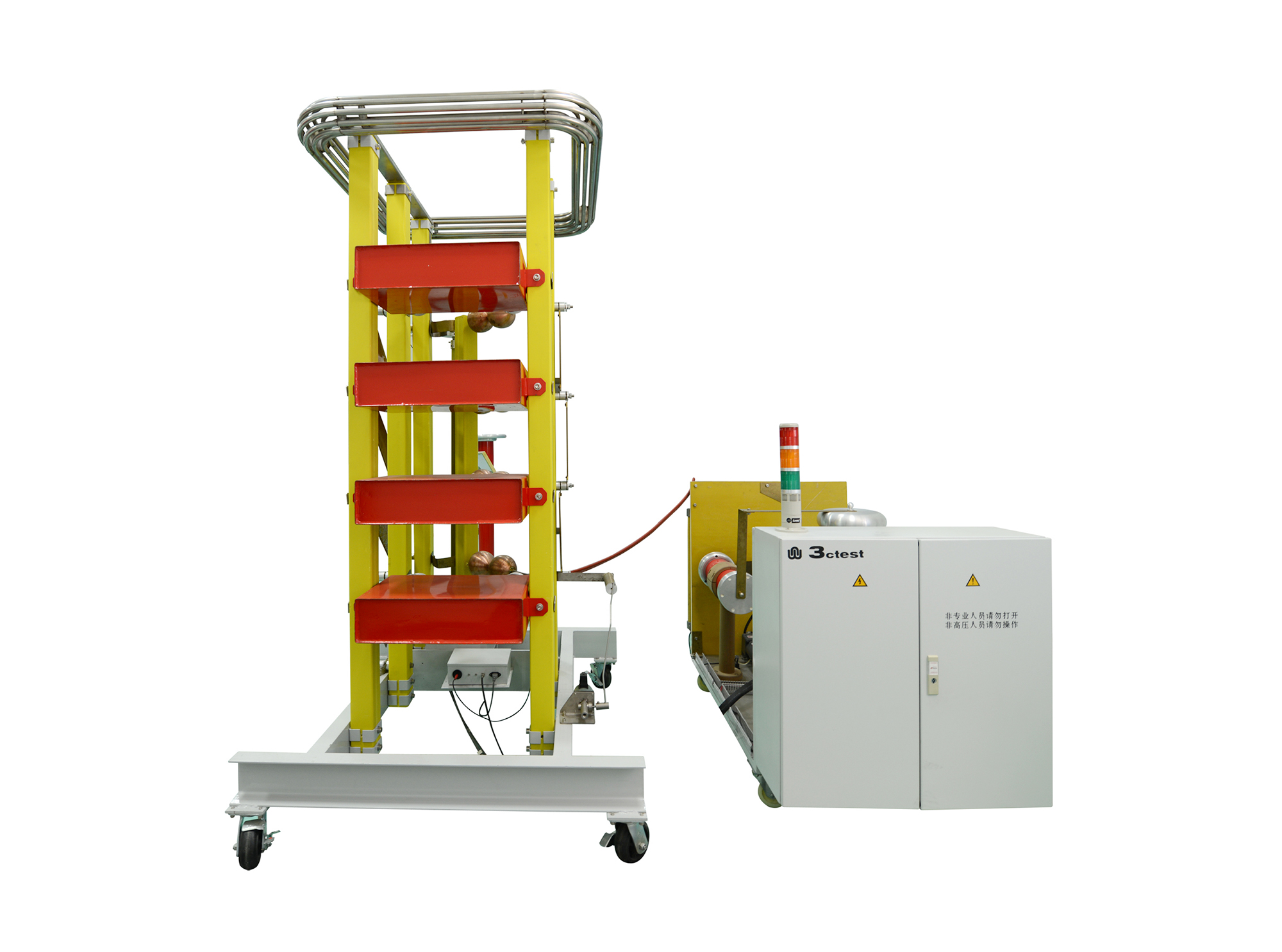
The LVG Series Impulse Voltage Test System is suitable for products rated at medium and low voltage levels. The wavefront and wave-tail resistors can be connected in parallel, while effective isolation gaps are provided between the wave-tail resistors to improve discharge synchronization. The wave-shaping resistors feature a plate-type structure without wire winding, allowing all synchronous discharge spheres to be installed inside sealed insulating tubes while continuously supplying filtered air. This design minimizes the influence of environmental changes on the spark gap, ensuring stable and reliable discharge performance. The system supports the generation of various impulse waveforms, including 1.2/50 μs.
> H-shaped frame with an elegant and robust design
> Automatic grounding system for enhanced safety and reliability
> Synchronous discharge ball mechanism with a gap adjustment accuracy of up to 0.1 mm
> Copper hemispherical electrodes with high-voltage pulse ignition, achieving a discharge synchronization rate of up to 99%
> Equipped with a movable base for convenient adjustment of the installation position
> Capacitive impulse voltage divider serves both to measure the peak value of the impulse output voltage and to provide the load capacitance
> Wave-shaping resistors feature a spring-clip mounting design for quick and tool-free replacement
> Reserved mounting platforms between stages for convenient equipment installation and stable access during maintenance
> Flexible operation with support for highly automated control and system integration

 Phone: +86-512-68413700
 Email: info@3ctest.cn
 Address:No.99 E'meishan Rd, SND, Suzhou, Jiangsu, 215153, China,Suzhou, Jiangsu, 215153, China



© 2025 Suzhou 3CTEST


 Leave a Message