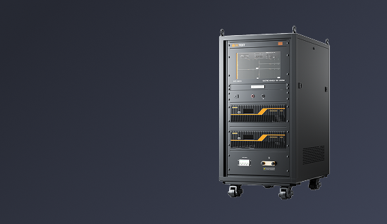
| Current Waveform 1 Cable Bundle Cable Induction |
| For tests as per DO-160G S22, MIL-STD-461G CS117(WF2/1) etc. |
| Coupling Mode | Cable Induction (CI) |
| Output Module | WAVE 1-CI/GI |
| Current Waveform 1 | 6.4 μs ± 20 % / 69 μs ± 20 % |
| Single Stroke Output | 50 A ~ 4,200 A (-0% ~ +20%);
Output impedance ≤0.5 Ω |
| Multiple Stroke Output | 50 A ~2,000 A (-0% ~ +20%) (first stroke);
Output impedance ≤0.5 Ω |
25 A ~ 1,000 A (-0% ~ +50%) (subsequent stroke);
Output impedance ≤0.5 Ω |
| Number of Subsequent Pulses | 1 ~ 14 |
| Interval of Subsequent Pulses | 10 ms ~ 200 ms, random mode is available |
| Polarity | Positive or negative |
| Number of Test Times | 1 ~ 99 |
| Test Repetition | 10 s ~ 99 s (shortest time depends on output amplitude) |
| Coupler | LCT-L5B |
| Current Waveform 1 Cable Bundle Ground Injection |
| For tests as per DO-160G S22 etc. |
| Coupling Mode | Ground Injection (GI) |
| Output Module | WAVE 1-CI/GI |
| Current Waveform 1 | 6.4 μs ± 20 % / 69 μs ± 20 % |
| Single Stroke Output | 50 A ~ 4,200 A (-0% ~ +20%);
Output impedance ≤0.5 Ω |
| Multiple Stroke Output | 50 A ~ 2,000 A (-0% ~ +20%) (first stroke);
Output impedance ≤0.5 Ω |
25 A ~ 1,000 A (-0% ~ +50%) (subsequent stroke);
Output impedance ≤0.5 Ω |
| The Number of Subsequent Pulses | 1 ~ 14 |
| Interval of Subsequent Pulses | 10 ms ~ 200 ms, random mode is available |
| Polarity | Positive or negative |
| Number of Test Times | 1 ~ 99 |
| Test Repetition | 10 s ~ 99 s (shortest time depends on output amplitude) |
| Max. EUT Power Supply | AC 230 V / 32 A 50/60 Hz;
DC 230 V/32 A |
| Coupler | LCT-L5B |
| Voltage Waveform 4 Signal Pins & Power Pins Direct Injection |
| For tests as per DO-160G S22 etc. |
| Coupling Mode | Pins Direct Injection (PDI) |
| Output Module | WAVE 4-PI |
| Output Impedance | 5 Ω ± 10 % |
| Voltage/Current Waveform 4 | 6.4 μs ± 20 % / 69 μs ± 20 % |
| Output Voltage | 50 V ~ 3,000 V (-0% ~ +10%), (open circuit) |
| Output Current | 10 A ~ 600 A (-0% ~ +10%), (short circuit) |
| Polarity | Positive or negative |
| Number of Test Times | 1 ~ 99 |
| Test Repetition | 10 s ~ 99 s
(shortest time depends on output amplitude) |
| EUT Power Supply | Max. 230 V |
| EUT Frequency | Max. 800 Hz |
| Power Blocking Device | > peak value of signal or power voltage (optional) |
| Voltage Waveform 4 Cable Bundle Ground Injection |
| For tests as per DO-160G S22 etc. |
| Coupling Mode | Ground Injection (GI) |
| Output Module | WAVE 4-CI/GI |
| Voltage Waveform 4 | 6.4 μs ± 20 % / 69 μs ± 20 % |
| Single Stroke Output | 50 V ~ 3,000 V (-0% ~ +20%);
Output impedance ≥0.5 Ω |
| Multiple Stroke Output | 25 V ~ 1,000 V (-0% ~ +20%) (first stroke);
Output impedance ≥0.5 Ω |
10 V ~ 500 V (-0% ~ +50%) (subsequent stroke);
Output impedance ≥0.5 Ω |
| The Number of Subsequent Pulses | 1 ~ 14 |
| Interval of Subsequent Pulses | 10 ms ~ 200 ms, random mode is available |
| Polarity | Positive or negative |
| Number of Test Times | 1 ~ 99 |
| Test Repetition | 10 s ~ 99 s
(shortest time depends on output amplitude) |
| Max. EUT Power Supply | AC 230 V / 32 A 50/60 Hz;
DC 230 V/32 A |
| Coupler | LCT-L5B |
| Voltage Waveform 4 Cable Bundle Cable Injection |
| For tests as per DO-160G S22 etc. |
| Coupling Mode | Cable Induction (CI) |
| Output Module | WAVE 4-CI/GI |
| Voltage Waveform 4 | 6.4 μs ± 20 % / 69 μs ± 20 % |
| Single Stroke Output | 50 V ~ 3,000 V (-0% ~ +20%);
Output impedance ≥0.5 Ω |
| Multiple Stroke Output | 25 V ~ 1,000 V (-0% ~ +20%) (first stroke);
Output impedance ≥0.5 Ω |
10 V ~ 500 V (-0% ~ +50%) (subsequent stroke);
Output impedance ≥0.5 Ω |
| The Number of Subsequent Pulses | 1 ~ 14 |
| Interval of Subsequent Pulses | 10 ms ~ 200 ms, random mode is available |
| Polarity | Positive or negative |
| Number of Test Times | 1 ~ 99 |
| Test Repetition | 10 s ~ 99 s
(shortest time depends on output amplitude) |
| Coupler | LVT-L5B |
| Voltage Waveform 5A Signal Pins & Power Pins Direct Injection |
| For tests as per DO-160G S22 etc. |
| Coupling Mode | Pins Direct Injection (PDI) |
| Output Module | WAVE 5A-PI |
| Output Impedance | 1 Ω ± 10 % |
| Voltage/Current Waveform 5A | 40 μs ± 20 % / 120 μs ± 20 % |
| Output Voltage | 50 V ~ 3,000 V (-0% ~ +10%) (open circuit) |
| Output Current | 50 A ~ 3,000 A (-0% ~ +10%) (short circuit) |
| Polarity | Positive or negative |
| Number of Test Times | 1 ~ 99 |
| Test Repetition | 10 s ~ 99 s
(shortest time depends on output amplitude) |
| EUT Power Supply | Max. 230 V |
| EUT Power Frequency | Max. 800 Hz |
| Power Blocking Device | > peak value of signal or power voltage (optional) |
| Current Waveform 5A Cable Bundle Cable Induction |
| For tests as per DO-160G S22, MIL-STD-461G CS117(WF4/5A) etc. |
| Coupling Mode | Cable Induction (CI) |
| Output Module | WAVE 5A-CI/GI |
| Current Waveform 5A | 40 μs ± 20 % / 120 μs ± 20 % |
| Single Stroke Output | 50 A ~ 10,000 A (-0% ~ +20%);
Output impedance ≤0.3 Ω |
| Multiple Stroke Output | 50 A ~ 2,000 A (-0% ~ +20%) (first stroke);
Output impedance ≤0.3 Ω |
25 A ~ 1,000 A (-0% ~ +50%) (subsequent stroke);
Output impedance ≤0.3 Ω |
| Number of Subsequent Pulses | 1 ~ 14 |
| Interval of Subsequent Pulses | 10 ms ~ 200 ms, random mode is also available |
| Polarity | Positive or negative |
| Number of Test Times | 1 ~ 99 |
| Test Repetition | 10 s ~ 99 s (shortest time depends on output amplitude) |
| Coupler | LCT-L5B |
| Current Waveform 5A Cable Bundle Ground Injection |
| For tests as per DO-160G S22, MIL-STD-461, CS117(WF4/5A) etc. |
| Coupling Mode | Cable Induction (GI) |
| Output Module | WAVE 5A-CI/GI |
| Current Waveform 5A | 40 μs ± 20 % / 120 μs ± 20 % |
| Single Stroke Output | 50 A ~ 10,000 A (-0% ~ +20%);
Output impedance ≤0.3 Ω |
| Multiple Stroke Output | 50 A ~ 2,000 A (-0% ~ +20%) (first stroke);
Output impedance ≤0.3 Ω |
25 A ~ 1,000 A (-0% ~ +50%) (subsequent stroke);
Output impedance ≤0.3 Ω |
| Number of Subsequent Pulses | 1 ~ 14 |
| Interval of Subsequent Pulses | 10 ms ~ 200 ms, random mode is also available |
| Polarity | Positive or negative |
| Number of Test Times | 1 ~ 99 |
| Test Repetition | 10 s ~ 99 s (shortest time depends on output amplitude) |
| EUT Power Supply | Max. AC 230 V / 32 A 50/60 Hz; DC 230 V/32 A |
| Coupler | LCT-L5B |
| Current Waveform 5B Signal Pins & Power Pins Direct Injection |
| For tests as per DO-160G S22 etc. |
| Coupling Mode | Pins Direct Injection(PDI) |
| Output Module | WAVE 5B-PI |
| Voltage/Current Waveform 5B | 1 Ω ± 10 % |
| Single Stroke Output | 50 μs ± 20 % / 500 μs ± 20 % |
| Multiple Stroke Output | 50 V ~ 1,600 V (-0% ~ +10%) (open circuit) |
| 50 A ~ 1,600 A (-0% ~ +10%) (short circuit) |
| Polarity | Positive or negative |
| Number of Test Times | 1 ~ 99 |
| Test Repetition | 10 s ~ 99 s (shortest time depends on output amplitude) |
| EUT Power Supply | Max. AC/DC 230 V |
| EUT Power Frequency | Max. 800 Hz |
| Power Blocking Device | > peak value of signal or power voltage (optional) |
| Current Waveform 5B Cable Bundle Cable Induction |
| For tests as per DO-160G S22 |
| Coupling Mode | Cable Injection (CI) |
| Output Module | WAVE 5B-CI/GI |
| Current Waveform 5B | 50 μs ± 20 % / 500 μs ± 20 % |
| Single Stroke Output | 50 A ~ 5,000 A (-0% ~ +20%)
Output impedance ≤0.3 Ω |
| Multiple Stroke Output | 50 A ~ 2,000 A (-0% ~ +20%) (first stroke);
Output impedance ≤0.3 Ω |
25 A ~ 1,000 A (-0% ~ +50%) (subsequent stroke);
Output impedance ≤0.3 Ω |
| Number of Subsequent Pulses | 1 ~ 14 |
| Interval of Subsequent Pulses | 30 ms ~ 200 ms, random mode is also available |
| Polarity | Positive or negative |
| Number of Test Times | 1 ~ 99 |
| Test Repetition | 10 s ~ 99 s (shortest time depends on output amplitude) |
| Coupler | LCT-L5B |
| Current Waveform 5B Cable Bundle Ground Injection |
| For tests as per DO-160G S22 |
| Coupling Mode | Ground Injection (GI) |
| Output Module | WAVE 5B-CI/GI |
| Current Waveform 5B | 50 μs ± 20 % /500 μs ± 20 % |
| Single Stroke Output | 50 A ~ 5,000 A (-0% ~ +20%);
Output impedance ≤0.3 Ω |
| Multiple Stroke Output | 50 A ~ 2,000 A (-0% ~ +20%) (first stroke)
Output impedance ≤0.3 Ω |
25 A ~ 1,000 A (-0% ~ +50%) (subsequent stroke);
Output impedance ≤0.3 Ω |
| Number of Subsequent Pulses | 1 ~ 14 |
| Interval of Subsequent Pulses | 10 ms ~ 200 ms, random mode is also available |
| Polarity | Positive or negative |
| Number of Test Times | 1 ~ 99 |
| Test Repetition | 10 s ~ 99 s (shortest time depends on output amplitude) |
| EUT Power Supply | Max. AC 50/60 Hz 230 V / 32 A; DC 230 V/32 A |
| Coupler | LCT-L5B |



 Phone: +86-512-68413700
 Email: info@3ctest.cn
 Address:No.99 E'meishan Rd, SND, Suzhou, Jiangsu, 215153, China,Suzhou, Jiangsu, 215153, China










 Leave a Message