
High frequency recommended vocabulary
This document primarily addresses the principles, system equipment configuration, test method introduction, and software closed-loop monitoring for low-frequency (DC–150 kHz) magnetic field immunity testing. It provides an overview of core technical specifications including radiation loops, Helmholtz coils, and field strength probes. Based on the volume of the equipment under test (EUT) and test requirements, the document analyzes the key factors influencing the selection of coils and field strength probes, as well as the specific application of software closed-loop monitoring and data analysis, thereby providing a theoretical basis and practical recommendations for testing.
Chapter 1: Test Overview
Test Purpose and Significance
To simulate low-frequency magnetic field interference present in real-world environments, evaluate the tolerance and functional performance retention of electronic components under such interference, and ensure their reliable and safe operation in actual vehicle conditions.
To ensure functional safety and driving safety — various low-frequency magnetic field sources exist inside and around the vehicle, which may cause interference to sensitive electronic circuits, particularly sensors based on the Hall effect and magnetoresistive effects, as well as inductive components, transformers, and other elements.
Test Requirements
The test frequency range specified in standards such as ISO 11452-8, GB/T 33014.8, and SAE J1113-21 is DC to 150 kHz, with an alternating magnetic field strength of 1000 A/m and a DC magnetic field strength of 3000 A/m, which covers the test level requirements of other automotive manufacturer standards.
Test Methods
Low-frequency magnetic field immunity testing involves applying a certain level of magnetic field interference to the EUT and monitoring its operating status to assess its immunity to magnetic field interference. The typical test methods for magnetic field immunity include the radiation loop method and the Helmholtz coil method.
Radiation loop method: The antenna is relatively small in size, offering high emission efficiency but poor field uniformity. For larger products, multiple separate exposures are required to cover the entire test envelope.
Helmholtz coil method: Lower emission efficiency but provides excellent field uniformity, making it suitable for testing moderately sized samples.
Test Frequency Conditions
The frequency range applies to DC (0 Hz) and 15 Hz to 150 kHz. Some automotive manufacturers extend the lower frequency limit down to 5 Hz.
The test frequencies shall include the following discrete points: 16.67 Hz, 50 Hz, 60 Hz, 150 Hz, and 180 Hz. The maximum frequency step sizes are shown in the table below:
| Frequency Band (kHz) | Linear Frequency Step (kHz) | Logarithmic Frequency Step (%) |
|---|---|---|
| 0 (DC) | — | — |
| 0.015~0.1 | 0.01 | 10 |
| 0.1~1 | 0.1 | 10 |
| 1~10 | 1 | 10 |
| 10~150 | 10 | 10 |
Test Magnetic Field Levels
The test levels, as well as the internal and external magnetic field test requirements, are determined based on the functional performance classification of the sample.
Table A.1 — Internal Magnetic Field Test Levels


Table A.2 — External Magnetic Field Test Levels


Chapter 2: Test System Configuration
The test equipment of the complete system includes the following components:
1) Field generating devices: radiation loop and Helmholtz coil;
2) Magnetic field strength monitor;
3) Low-frequency generator;
4) Low-frequency amplifier;
5) Voltmeter;
6) Current monitor;
7) Artificial network (AN) — used solely to establish the power supply circuit and unrelated to the interference source.

Schematic diagram of test setup
1. Field Generating Devices
The field generating devices include the radiation loop and the Helmholtz coil. For the radiation loop, the field strength H at a distance of 50 mm from the loop plane is calculated as H (50 mm) = 75.6 × I, where H is the magnetic field in A/m, 75.6 is the constant in m, and I is the current in the coil in A. Under ideal conditions, the Helmholtz coil establishes a uniform magnetic field region of at least 300 mm × 300 mm × 300 mm. The field strength at the center of the Helmholtz coil is H = 0.7155 × N × I / R, where H is the magnetic field in A/m, 0.7155 is the constant, N is the number of turns, R is the coil radius in m, and I is the coil current in A.
1) DC Radiation Loop TBR 300, DC Radiation Loop TBR 1500

DC Radiation Loop TBR 300 specifications: diameter 120 mm; 20 turns; magnetic field strength ≥ 3000 A/m; maximum current 20 A (DC); 2 mm diameter copper wire;
DC Radiation Loop TBR 1500 specifications: diameter 120 mm; 225 turns; magnetic field strength ≥ 15000 A/m; maximum current 20 A (DC); 2 mm diameter copper wire;
2) AC Radiation Loop TBR 100
AC Radiation Loop TBR 100 specifications: diameter 120 mm; 20 turns; magnetic field strength ≥ 1000 A/m @ 1 kHz, ≥ 10 A/m @ 150 kHz; maximum current 20 A; 2 mm diameter copper wire; frequency range DC to 150 kHz;
3) DC Helmholtz Coils TYXH 03300, TYXH 06300, TYXH 1300

TYXH 03300 specifications: maximum current 20 A; magnetic field ≥ 3000 A/m; coil factor 152; diameter 300 mm; inductance ≤ 2.5 mH; DC resistance ≤ 0.6 Ω;

TYXH 06300 specifications: maximum current 20 A; magnetic field ≥ 3000 A/m; coil factor 152; diameter 600 mm; inductance ≤ 15 mH; DC resistance ≤ 1.6 Ω;

TYXH 1300 specifications: maximum current 30 A; magnetic field ≥ 3000 A/m; 150 turns; diameter 1000 mm;
4) AC Helmholtz Coils TYXH 03100, TYXH 06100

TYXH 03100 specifications: frequency DC to 150 kHz; maximum magnetic field ≥ 1000 A/m @ 1 kHz, ≥ 10 A/m @ 150 kHz; diameter 300 mm; maximum current 20 A (RMS);

TYXH 06100 specifications: frequency DC to 150 kHz; maximum magnetic field ≥ 1000 A/m @ 1 kHz, ≥ 10 A/m @ 150 kHz; diameter 600 mm; maximum current 20 A (RMS);
2. Current Monitor
The current monitor shall be capable of measuring RMS current over the frequency range of DC and 15 Hz to 150 kHz, achieved either through a clamp-on current probe or by measuring the voltage across a shunt resistor.

3. Magnetic Field Strength Monitor
The purpose of the magnetic field strength monitor is to measure the actual magnetic field generated by the radiation loop, rather than calculating the field strength from current monitoring. For DC, the magnetic field strength monitor shall be based on a Hall-effect sensor or equivalent measuring instrument. A typical magnetic field strength monitor for DC should be capable of measuring at least 3000 A/m.

Hall Sensor HS 5136
The output of the Hall sensor is also connected to the voltmeter for reading. The HS 5136 sensor has a conversion ratio of 1000:1, i.e., 1 mV corresponds to 1 A/m. This verifies the accuracy of the field strength generated by the current method. For AC, a field strength probe or loop sensor shall be used for monitoring, with the output converted to a voltage value and measured with a multimeter. The recommended field strength probe has a diameter of 40 mm and 51 turns. A typical field strength probe can measure at least 1000 A/m over the range of 15 Hz to 150 kHz. The lower frequency limit can be extended to 5 Hz.

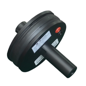
Two types of field strength probes

4. Low-Frequency Generator + Low-Frequency Amplifier
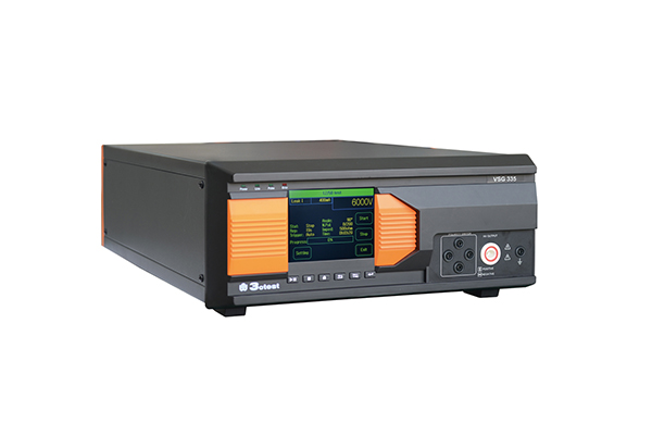
The RSG 40C20S is primarily used to generate DC voltage and low-frequency sinusoidal output covering up to 150 kHz, providing sufficient current to enable the field generating device to produce a field strength of no less than 3000 A/m.

Frequency range: DC to 300 kHz; Open-circuit output voltage MAX 80 Vpp; Maximum current 20 A (RMS); Maximum power consumption 800 W;
5. Voltmeter
A 6.5-digit voltmeter with high precision is used to monitor the voltage across the shunt resistor or the current value from the clamp-on current probe, thereby enabling field strength adjustment.

6. Artificial Network (AN)

Chapter 3: Test Method Description
The test harness shall be designed to minimize coupling effects within the harness and to reduce interference to the load box and power supply. The test harness and EUT shall be placed on non-conductive, non-magnetic, low-permeability supports, such as wooden tables or support plates.
1. Radiation Loop Method
Each face of the EUT shall be divided into equal areas of no more than 100 mm × 100 mm. The radiation loop shall be positioned 50 mm from the center of each of these areas, parallel to the face of the EUT. In addition, the radiation loop shall also be placed at each electrical interface connector and at all magnetic sensor locations. That is, radiated testing on faces, radiated testing on electrical interfaces, and radiated testing on magnetic sensors.


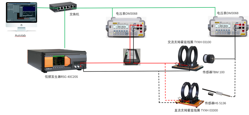
Schematic diagram of test setup connections
Software connection configuration: low-frequency generator + low-frequency amplifier; monitoring of sensor list values. By acquiring the voltage across the shunt resistor, the software obtains the voltage reading from the multimeter, converts it to current, calculates the field strength, and performs closed-loop calibration.


After calibration, the Hall sensor can be used to verify the field strength value of the DC radiation loop. During verification, the multimeter monitoring the shunt resistor is no longer required.

Schematic diagram for Hall sensor verification of DC radiation loop field strength — 1 mV : 1 A/m
After calibration, the field strength probe is used to verify the field strength value of the AC radiation loop. The conversion voltage value shall be calculated against the field strength probe correction factors provided by the manufacturer.


2. Helmholtz Coil Method
The DUT shall be placed on a non-conductive, low-permeability material within the uniform field region of the Helmholtz coil, oriented along one of the three principal axes (X, Y, and Z). The DUT harness shall be routed vertically downward, away from the coil and monitoring equipment.


The test method and principle here are identical to those of the radiation loop method, and the software operation is also the same; therefore, details are not repeated here.

Chapter 4: Test Procedure
The test plan shall include the test setup, test levels, and any deviation from standard test conditions and setups shall be recorded in the test report. The DUT shall be operated under typical loads and actual operating conditions. For the radiation loop method, the test points on the DUT shall be specified. For the Helmholtz coil method, the X, Y, Z axes of the DUT shall be specified, and the acceptance criteria and monitoring conditions for the DUT shall be defined before testing begins.

Radiation loop method testing shall be performed with three axial polarizations, covering test points including faces, electrical interfaces, and magnetic sensor locations. The distance from the coil is 50 mm. At each frequency point, the EUT shall be exposed for at least 1 second. Any malfunction of the EUT shall be monitored and the corresponding field strength recorded. Repeat the above steps to complete testing for all face, electrical interface, and magnetic sensor test points.
The Helmholtz coil method setup is the same as that of the radiation loop method, except that the sample is placed at the center of the coil rather than on the insulating wooden support plate. The EUT shall be exposed for at least 1 second at each frequency. If any malfunction of the EUT occurs, record the corresponding frequency and field strength. Repeat the above test for the other two axes.

EUT positioned at the center of the uniform field region
 Phone: +86-512-68413700
 Email: info@3ctest.cn
 Address:No.99 E'meishan Rd, SND, Suzhou, Jiangsu, 215153, China,Suzhou, Jiangsu, 215153, China



© 2025 Suzhou 3CTEST

 Leave a Message