
High frequency recommended vocabulary
Contents
Part 1. Overview of Impulse Voltage Withstand Test
Part 2. Generation Mechanism of the 1.2/50μs Impulse Voltage Waveform
Part 3. Differences in Test Requirements Among Different Standards
Part 4. Selection Strategy for Impulse Voltage Generators
Part 1. Overview of Impulse Voltage Withstand Test
1. Test Purpose and Significance
Core definition: The impulse voltage withstand test (also known as the surge voltage test) is a verification of whether the insulation system of equipment can withstand transient overvoltages (such as lightning strikes or switching overvoltages in the power grid) that may occur in actual use.
Evaluation target: It mainly assesses the reliability of clearances, solid insulation, and creepage distances under transient high voltage. This test does not check functional performance (e.g., whether the equipment shuts down), but rather safety aspects (e.g., whether it catches fire or breaks down).
2. Key Waveform Parameters (1.2/50μs)
Terms and definitions:
Front time T₁: Apparent parameter, defined as 1/0.6 times the time interval T between the 30% and 90% points (points A and B in Fig.1) of the peak voltage of the test waveform.
Time to half value T₂: Apparent parameter, defined as the time interval from the virtual origin O₁ to the instant when the test voltage falls to half of its peak value.
Effective output impedance: The ratio of the open-circuit voltage peak to the short-circuit current peak measured at the same output terminal of the surge generator.

Fig.1 Waveform (GB/T 17627:2019)
3. Application Scenarios
Power adapters, battery chargers, household appliances (refrigerators, air conditioners), industrial measurement relays, information technology equipment (computers, servers), etc., covering audio/video, information technology, and communication technology equipment.
Part 2. Generation Mechanism of the 1.2/50μs Impulse Voltage Waveform
The 1.2/50μs impulse voltage waveform is produced by the transient discharge of an RLC series circuit. Its core principle is to use capacitor energy storage and shaping by inductors, capacitors, and resistors to generate a single high‑voltage pulse that meets standard specifications.
Typically, both unipolar RLC pulse circuits and Marx‑generator plus RLC pulse circuits are used.
Three stages: charging, discharging, and waveform shaping.

Fig.2 Impulse waveform schematic (GB 4943.1:2011)
Part 3. Differences in Test Requirements Among Different Standards
1. IEC 60060‑1:2010 / GB/T 16927.1:2011, High‑voltage test techniques – Part 1: General definitions and test requirements.
IEC 61180:2016 / GB/T 17627:2019, High‑voltage test techniques for low‑voltage equipment – Definitions, test and procedure requirements, and test equipment.

Fig.3
2. IEC 62368‑1:2023 / GB 4943.1:2011, Audio/video, information and communication technology equipment – Part 1: Safety requirements.

Fig.4


Fig.5

Fig.6
3. IEC 60335‑1:2020 / GB 4706.1:2024, Household and similar electrical appliances – Safety – Part 1: General requirements.

Fig.7

Fig.8
4. IEC 61009‑1:2024 / GB/T 16917.1:2014, Residual current operated circuit‑breakers with integral overcurrent protection for household and similar uses (RCBOs).


Fig.9
5. IEC 60255‑27:2023 / GB/T 14598.27:2025, Measuring relays and protection equipment – Part 27: Product safety requirements.

Fig.10
6. Summary

Calibration method: No‑load calibration.
Part 4. Selection Strategy for Impulse Voltage Generators
1. Distinction Between Impulse Voltage Withstand Test and Lightning Surge Test
Common mistake: Test engineers often mistakenly use a lightning surge generator for impulse voltage withstand testing. This is incorrect.
1.1 Different Test Purposes
Table 1

1.2 Different Standard References
Table 2

1.3 Different Waveforms
Table 3

1.4 Different Output Impedance
Table 4

1.5 Different Pass/Fail Criteria
Table 5

1.6 Summary
The impulse voltage withstand test and the lightning surge test are two completely different tests, belonging to the safety (product safety) and EMC domains, respectively.
Table 6

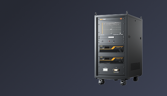
2. Selection
Table 7


 Phone: +86-512-68413700
 Email: info@3ctest.cn
 Address:No.99 E'meishan Rd, SND, Suzhou, Jiangsu, 215153, China,Suzhou, Jiangsu, 215153, China



© 2025 Suzhou 3CTEST

 Leave a Message