
cn
Power Failure Simulator_PFS 150100T1
  • Power Failure Simulator_PFS 150100T1
  • Power Failure Simulator_PFS 150100T1
  • Power Failure Simulator_PFS 150100T1

Power Failure Simulator
PFS 150100T1

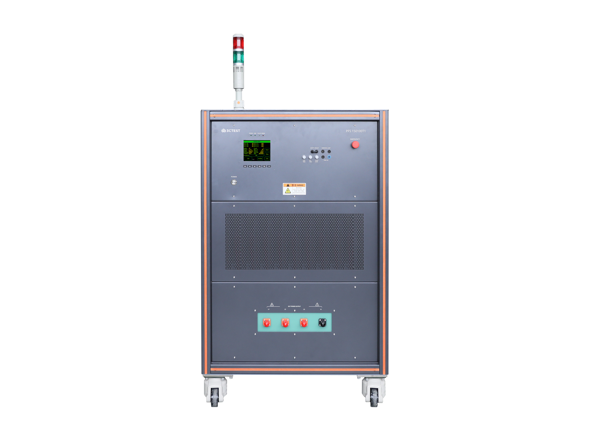
The PFS 150100T1 power failure simulator is based on the company’s new-generation control platform and designed according to IEC 61000-4-34. 

Introduction

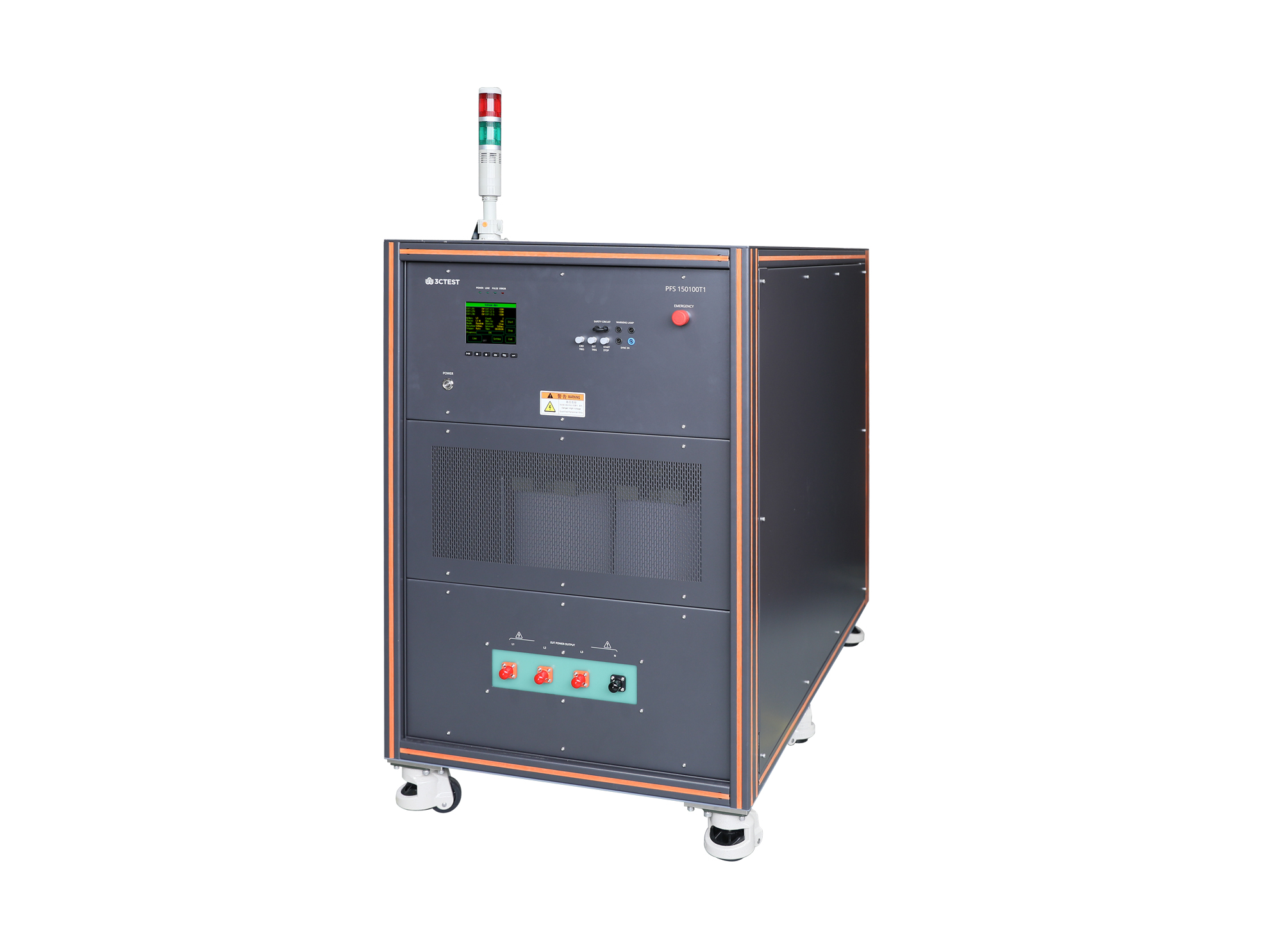
The PFS 150100T1 power failure simulator is based on the company’s new-generation control platform and designed according to IEC 61000-4-34. It simulates voltage dips and short interruptions at the power input port caused by grid or substation faults and sudden load changes.


The PFS 150100T1 is equipped with a controllable semiconductor switch that withstands inrush currents above 1,000 A and features electronic short-circuit protection. These tests evaluate whether electrical and electronic equipment can avoid unsafe operating conditions under sudden voltage changes.


Features

> 5.7-inch color touchscreen for front panel operation

> Max. output voltage 1,500 V AC, Max. continuous current 102 A

> Real-time voltage and current acquisition for comprehensive monitoring of test conditions

> Built-in multifunctional test module combination

> Built-in overvoltage, overcurrent, voltage limiting and current limiting protection

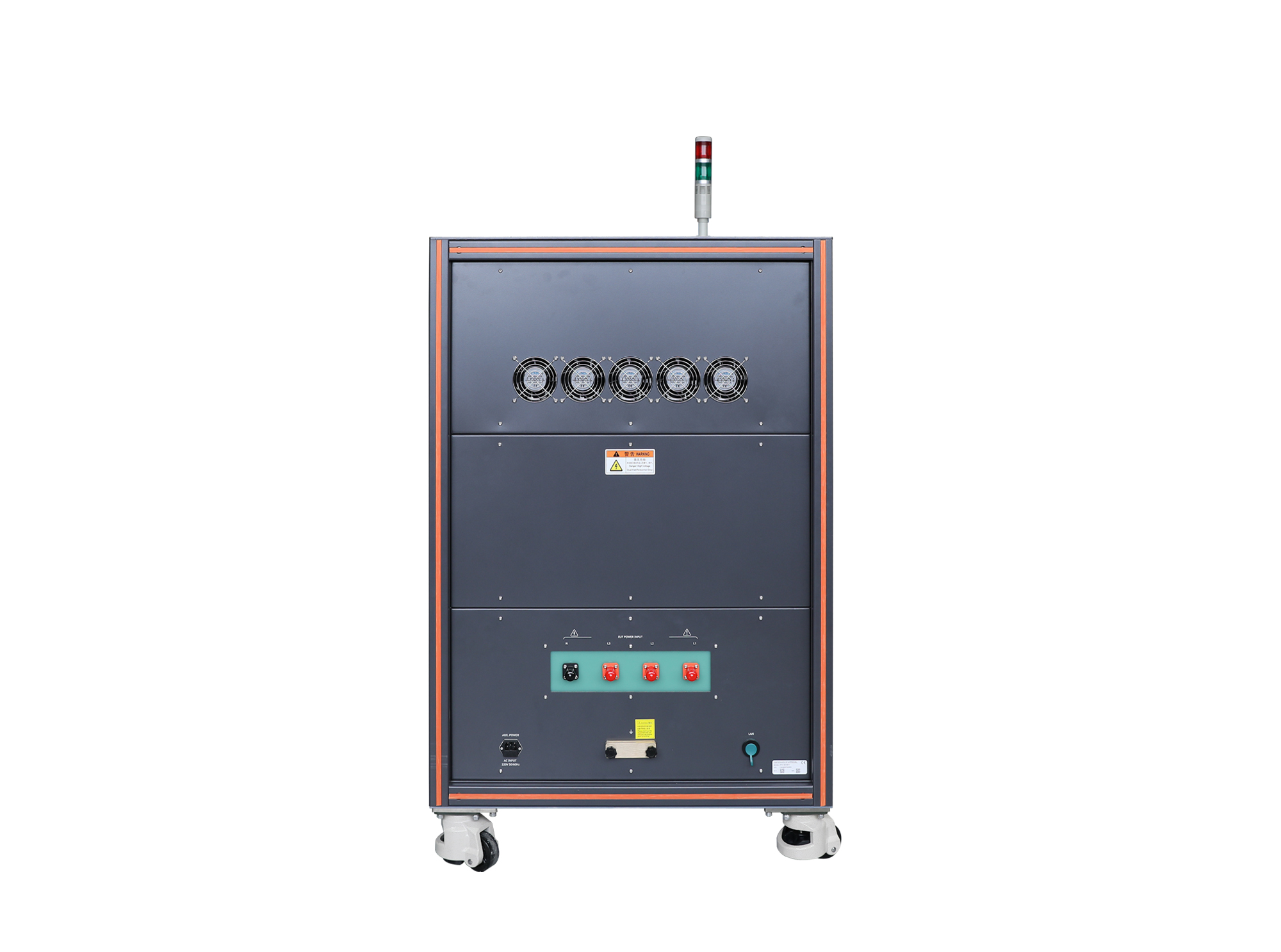
> Ethernet RJ45 interface for PC remote control and test report printing

> Optimized arc suppression and waveform control for accurate grid fault simulation and stable waveforms under high-voltage and high-current conditions.

Standards
IEC Standards
GB/T Standards
EN Standards
Specification
Technical Parameters
EUT Max. Input Voltage1,500 V AC, 50 Hz /60 Hz
EUT Voltage and Current MeasurementLCD display
Max. Continuous EUT Current102 A
Inrush Current Withstand Capability>1,000 A
ProtectionBuilt-in overcurrent, short-circuit, overvoltage, overtemperature, surge, EFT/burst and ESD protection.
Optional external protection accessories for Line in/Line out ports (e.g. warning lights, emergency stop buttons)
Interruption Level0%
Voltage Dip Level0%, 40%, 70%, 80%
Voltage Dip and Interruption Duration0.3 ~ 9,999 cycles or 10 ms ~ 99,999 ms
Voltage Dip and Interruption Interval50 ms ~ 50,000 ms
Voltage Dip and Interruption Counter1 ~ 9,999
Voltage Dip and Interruption Rise/Fall TimeGenerator rated current >75 A: 1 μs ~ 50 μs (resistive calibration specified in the standard)
Synchronization0° ~ 360°, 1° step setting or random mode
Trigger ModeManual, automatic, external trigger input
General Parameters
Accessories
Optional Accessories
1Immunity Test SoftwareModel: CoreLab
> Support Windows 7/8/10 /11
> Supports Ethernet and serial communication modes
> Supports parameter sequence, test sequences, easy for operation
> Supports customer information configuration and automatic test report printing.
CoreLab.png
2Calibration Impedance BoxModel: R100Ω/1134
Impedance: 100 Ω
Accuracy: ± 10%
Power: 2,000 W
Generator rated current: ≤50 A
R25.png
Model: R50Ω/1134
Impedance: 50 Ω
Accuracy: ± 10%
Power: 3,000 W
Generator rated current: 50 A<I≤100 A
Model: R25Ω/1134
Impedance: 25 Ω
Accuracy: ± 10%
Power: 6,000 W
Generator rated current: >100 A
Request a Quote
Interested in our products? Leave us a message, and our team will get back to you soon!
  • Search Engine
  • Industry Exhibition / Trade Show
  • Social Media
  • Online Advertisement
  • Industry Publication
  • Business Partner / Distributor
  • Colleague or Industry Contact
  • Existing Customer
  • Other
I agree to the  Privacy Policy.

If you have any questions, feel free to Contact Us!

Prev: Single-phase Power Failure Simulator Next: Power Disturbance Simulator Back to list
Request a Quote Now
Power Failure Simulator
PFS 150100T1
  • Search Engine
  • Industry Exhibition / Trade Show
  • Social Media
  • Online Advertisement
  • Industry Publication
  • Business Partner / Distributor
  • Colleague or Industry Contact
  • Existing Customer
  • Other
Quote List0
Compare0
Selection
Top
Compary
Add up to 5 product comparisons for each type.
Only compare the currently expanded module.